Topology
5 minute read
You can create a network topology map either using the Create Docu wizard, the Topology wizard or in the tree by clicking on the Topology map or VLAN Map node.
A network topology map shows the interrelations of switches, virtual switches and systems in a network environment. Switches are scanned using an SNMP systems inventory scan. For virtual switches, you need to perform a VMware Infrastructure inventory scan.
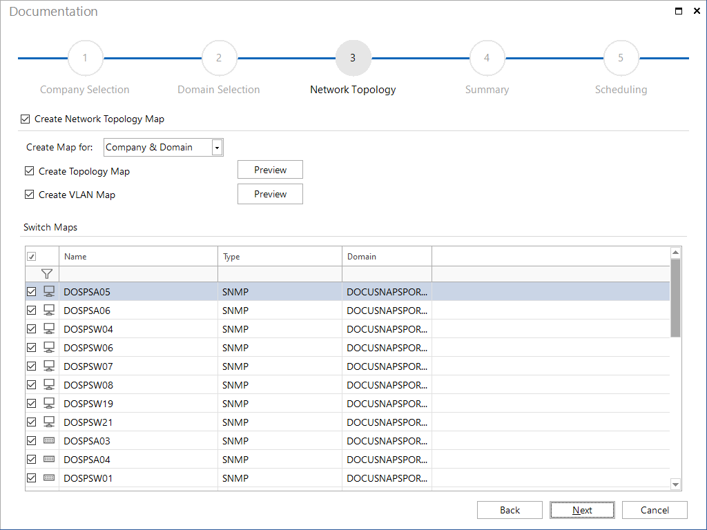
Documentation Wizard
In the Create Map for combobox, you can select whether the maps are to be created for the Company & Domain, for the Domain only, or for the Company only. Only domains selected in the Domain Selection step are considered.
In the maps for the company, all selected domains are combined in one map.
Use the Ignore Virtual Structures checkboxes to determine, if the Topology Maps and the VLAN Maps should include virtual structures.
Docusnap will generate additional maps for switches and virtual switches that have been selected in the Switch Maps table. These maps will show the systems connected to the selected switch.
Click on the Preview button to open a preview of the maps, in which further settings can be defined.
The maps for the company will be stored in the Maps folder below the company.
(\Documentation Path\Company\Maps\topology)
If you create the maps for the domain, the Visio and html files will be stored in the Maps folder of that domain.
(\Documentation Path\Company\Domain\Maps\topology)

Ad hoc map in the tree
The maps can be created by clicking on the Topology Map or VLAN Map node in the tree.These maps are always created using the current data and are generated each time they are opened. The optional settings can also be made for the ad hoc plans.
Topology Map Options
Edit Systems: Opens a dialog for switch selection and restricts the detailed topology plans to these devices.
Special
- Potential Access Points: Non-inventoried endpoints, usually access points, are displayed in the map by applying network topology discovery protocols (CDP, LLDP).
- Layer3 Elementes: End devices such as firewalls or servers that have redundant connections to several switches can be hidden in the map with this option.
- Tunnel Connection: Tunnel connections detected via LLDP or CDP are displayed in the map.
VLAN
- VLAN Tables: The VLAN configurations of the switches are displayed in a table; identical configurations are given the same background color.
- Port with VLAN Information: The detailed plans of the switches hereby show the VLAN information for each switch port. Ports without VLAN settings are marked as untagged ports, while ports with VLAN settings are shown with a table of configured VLANs per port.
- Show only Used VLANs: Only display VLANs for which endpoints have been detected, and require that the option Port with VLAN Information is enabled.
Details
- Switch Details: Displays detailed information for each switch port, for example, such as the manufacturer of the connected devices by analyzing the MAC address.
- Cable Bandwidth: Connections between the switches are displayed with the corresponding bandwidth information.
- Port Names: In the overview plan, the connections between the switches are labeled with port numbers that indicate the ports via which the switches are connected to each other.
Virtual
- Virtual Structures and Switches: Add virtual switches to the topology visualization, display them in the overview map, and create detailed maps for each virtual switch.
Visualization
- Visualize Cable Bandwidth: With this option, connections are displayed in different colors and thicknesses depending on their bandwidth. Lines representing speeds over 10GB appear blue and six pixels wide. Connections with 1GB are green and three pixels wide. For connections under 1GB, the lines are red and one pixel wide.
- Highlight Missing Data: Switches are marked if LLDP, CDP, STP, learned MAC addresses, or interface stack data are missing. By right-clicking on the marked object and selecting Show Data, the error message is displayed in a separate dialog.
VLAN Map Options
Special
- Access Points: The Access Points option allows you to specify whether devices that were recognized as access points during the inventory should be included in the topology map.
- Potential Access Points: Non-inventoried endpoints, usually access points, are displayed in the map by applying network topology discovery protocols (CDP, LLDP).
- Layer3 Elementes: End devices such as firewalls or servers that have redundant connections to several switches can be hidden in the map with this option.
VLAN
- Show only Used VLANs: Only display VLANs for which end devices have been detected.
- Filter on relevant switches (from the Viewpoint of the VLAN):* The detailed plan of a VLAN is restricted to the switches relevant for this VLAN. Only the switches that are actually connected to the selected VLAN appear in the detailed plan.
Virtual
- Virtual Structures and Switches: Add virtual switches to the topology visualization, display them in the overview map.
Details
- Switch Details: Displays detailed information for each switch port, for example, such as the manufacturer of the connected devices by analyzing the MAC address.
- Cable Bandwidth: Connections between the switches are displayed with the corresponding bandwidth information.
- Port Names: In the overview plan, the connections between the switches are labeled with port numbers that indicate the ports via which the switches are connected to each other.
Analysis and Verification of VLAN Settings
Detailed maps for each VLAN are created to verify the switch configurations. Switches that are not configured for the respective VLAN are marked in red on the map.
Connections that fail due to missing VLAN information or communication issues are also displayed in red. This can indicate missing configurations or insufficient information.
The detailed map of a VLAN displays all switches, with devices not configured for the respective VLAN marked in red. The option Filter to Relevant Switches shows only the switches that successfully communicate with the VLAN.